ASCII display station
187-132
3151 ASCII Display Station
189-071
New Models And Enhancements (510/560 and 610/660)
Common
Problems and Questions About 3151 Terminals
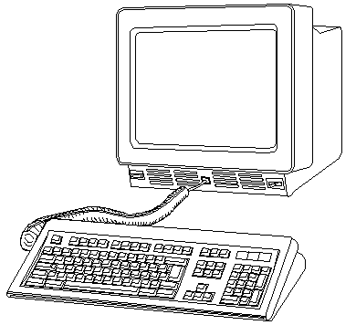
The IBM 3151 ASCII Display Station
is a two-element workstation that provides attachment capabilities to both
IBM and non-IBM processors. A native mode and 10 non-IBM emulation
modes are included in the base of all models. The Model 110 should
be used for
entry level applications requiring an 80-column display. Models
310
and 410 (which are functionally identical to each other except for
the color of the display phosphor) should be used with applications that
require 80- or 132-characters-per-line capability, 3101 emulation, a dedicated
numeric keypad, Program Access (PA) keys, greater than 12 function keys
or RS422A capability via cartridge. Additional emulations and attachment
capabilities are provided in two new slim-line cartridges for Models 310
and 410.
The IBM 3151 Cartridge for Emulating IBM and DEC Terminals provides
the ability for IBM 3151 Models 310/410 and 360/460 to support RS422A communications
for the emulations provided on that cartridge. The RS422A interface
supports a point-to-point direct coupling with a maximum cable length of
4,000 feet.
The main communications port has
a selectable transmission rate from 50 bps to 38,400 bps, inbound and outbound
XON/XOFF pacing (inbound pacing is the default and not selectable), and
echo/character/block modes, and supports seven- or eight-bit word length
and no/odd/even/mark and space for parity.
The auxiliary port on the 3151
Model 110/160 is a unidirectional RS232C port for attaching another asynchronous
ASCII device such as an ASCII printer. On IBM 3151 Models 310/410
and 360/460 the auxiliary port is enhanced with a bidirectional data capability.
This allows the attachment of output devices, such as a printer, as well
as input devices, such as wands and ASCII terminals. Transmission rates
from 50 bps to 19,200 bps are selectable independent of the main communications
port speed settings.
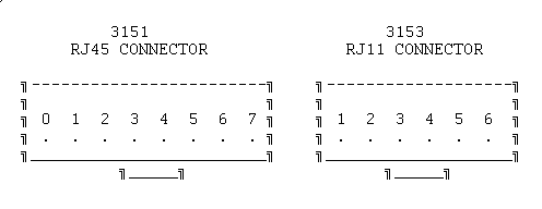
The 3151 and 3153 keyboards are not interchangeable. The following
is a diagram of the modular RJ keyboard connector:

|
PIN
|
3151 NAME
|
PIN
|
3153 NAME
|
|
0
|
NO CONNECTION
|
1
|
KBD CLOCK
|
|
1
|
FRAME GROUND
|
2
|
KBD DATA
|
|
2
|
+5
|
3
|
RESET*(PULLED UP TO +5V)
|
|
3
|
KBD DATA
|
4
|
SIGNAL GROUND
|
|
4
|
KBD CLOCK
|
5
|
+5V
|
|
5
|
SIGNAL GROUND
|
6
|
FRAME GROUND
|
|
6
|
FRAME GROUND
|
|
|
|
7
|
NO CONNECTION
|
|
|
These pins and connector drawing are relative to the connector on the
3151, 3153 video element. These pins and connectors are not relative
to the connector on the keyboard coiled cable.
Which port is the main communication port?
If you look at the back of the 3151, the main port
is on the right-hand side, closest to the edge. The auxiliary port
is closest to the power cord.
Anyone know why I don't have the option for an ASCII display under
Set Console? I tryed it on my 9595-0LF and 9595-3PT. Neither one
has it. The 9595-0LF did go into "96-8N1" mode by itself about
a month ago but it won't now that I want it to!
I have a "IBM Cartridge to emulate IBM and DEC terminals" P/N 94X4114.
Of course nothing works with or without it installed ...
Hi Dennis !
You need a nullmodem cable for the terminal and no cartridge
installed (native mode). The terminal test switch must be in "normal".
The 9595 should be configured to "keyboard and videoless
mode" somewhere in additional features. Then the video card must be removed
to force the machine to kickstart the ASCII-terminal at COM1.
There should be a chapter on using the ASCII console in
the EPRM ...
Your server supports the specialized use of some ASCII display stations
instead of a display and a keyboard. The following IBM ASCII display
stations can be attached to a serial port: 3151, 3161, 3162, 3163,
and 3164.
Keep in mind if you plan to use an ASCII display station:
o You need to verify that your operating system supports an ASCII display
station. Not all operating systems provide such support.
o Beginners All-Purpose Symbolic Instruction Code (BASIC) language
is not supported when you use an ASCII display station.
o High-resolution graphics (icons and graphic-based programs) are not
available when you use an ASCII display station.
o Power-on self-tests (POST) text messages and logs are not available
on ASCII display stations.

Use the setup instructions that came with your ASCII display station
and the information in this section to attach it to your server.
Notes:
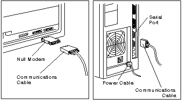
1. You must use a null-modem cable or connector with your communication
cable. Without one, the ASCII display station has no communications link
with the server. (You can buy a null-modem cable or connector from
your dealer.)
2. If your ASCII display station has a test switch next to the
keyboard connector, make sure it is in the normal position, not the test
position.
3. When you use the system programs to define the setup values
on the ASCII display station, be sure the machine mode of the terminal
matches the actual display station you are installing. For example,
if you are installing a 3151 ASCII Display Station, you must set the Machine
Mode on the terminal Setup Menu to IBM3151.When the setup values correctly
match the display station type, the machine is considered to be in the
native-machine mode.
To set up your ASCII display station:
1. Attach the null-modem connector to the communication
cable and to the back of the ASCII display station.Connect the other end
of the cable to one of the serial connectors on the back of your server.
Note:
If you have enabled the serial port power-on mode, do not attach your ASCII
display station to serial port A. You must use serial port B.
Connect the power cord to the back of
the server; then, plug it into a properly grounded electrical outlet.
Follow the instructions that came with
the ASCII display station to connect the power cable to the ASCII display
and to plug it into a properly grounded electrical outlet.

2. Turn on the ASCII display station and make sure it is
in native-machine mode. (See note 3 at the beginning of this section.)
3. Set the communication values on the display station:
a. Press Ctrl and Setup to display the
General Setup Menu.
b. Press Send to display the Communication
Setup Menu.
c. Review the communication values and
compare them to the values shown below.
Line Speed (bps)
9600
Word Length (bits)
8
Parity
No
Stop Bit
1
d. If you need to change a value, move
the cursor to highlight that value, then press the space bar to display
alternative values.
e. When all the communication values
match the values specified in this section, press Send twice to display
the Function Menu.
f. Move the cursor to the Save data
field and press the space bar to store these values.
Notes:
a. When using the system programs, do
not install an emulation cartridge unless it will support native-machine
mode.
b. The display stations designed for
countries where English is not the native language must support the International
Standards Organization (ISO) 8859/1.2 code page. Some of the display
stations require a cartridge to support this code page. Check the information
supplied with your display station to determine if a cartridge is required.
c. For additional information about
communication values, refer to the documentation that was supplied with
your ASCII display station.
4. Verify that all the correct values have been stored:
a. Move the cursor to the Recall data
field. This displays the current communication values. (Your
server uses these during configuration process.)
b. Press Ctrl and Setup to exit.
Only the cursor will be displayed on the screen.

5. Start the system programs.
o If you are using an ASCII display station:
a. Insert the Reference
Diskette in the diskette drive.
b. Turn on the ASCII
display station and the server.
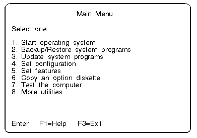
c. When the cursor
moves to the top-right corner of the screen, press and hold Crtl and I.
(the letter i) to view the Main Menu of the system programs.
o If you are using a keyboard and a display:
a. Insert the Reference
Diskette in the diskette drive.
b. Turn on the server
and allow the power-on self-tests (POST) to finish.
c. Press F1 to view
the Main Menu of the system programs.

6. Change the Console Select settings to indicate that
you are using an ASCII display station.
Warning: Before you make any changes
using the Console Select program, make sure you have an ASCII display station
attached to the server. If you do not, there will be no way for you
to communicate with the server.
When you are at the Main Menu,
a. Select Set features; then, press
Enter.
b. Select Set console from the Set Features
Menu; then, press Enter.
c. Select ASCII display station from
Set Console Menu; then, press Enter.
7. Make sure the values are set as shown:
Baud rate
9600
Bits per character
8
Parity
None
Stop bits
1
Any time you change the ASCII display
station values, you must also update the system unit values to match.
The baud rate should always be 9600 or above. If you set the baud
rate below 9600, the system performance decreases.
Note: These instructions
assume that the display station has already been set to these values (see
step 3 of this procedure).
Some server operations change when you use an ASCII display station
(see the following list).
Communication
When you are using an ASCII display station, the communication parameters
will appear on the information panel (for example, 96-8N1). This
information is not an error message.
Configuration
When you run the server setup programs, system programs, or diagnostics
programs from the ASCII display station, the display station values might
change. If display problems occur after you run these programs, check
the display station values. To check these values, press Ctrl and Setup.
Modify the values if necessary.
Utility Programs To start the server
system programs when using an ASCII display station, insert the Reference
Diskette into the startup drive. Turn on your server.
Note:
To restart your server after running the utility programs, press and hold
Ctrl, then press C, A, and D. Release C, A, and D. Then, release
Ctrl.
Diagnostic Tests When you select
an ASCII display station as the system console, the keyboard, mouse, system
board async port, and video displays will not on the diagnostic Installed
Device list.
9595 Main
Page
|


