|
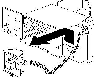
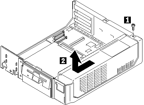
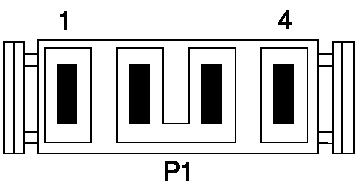
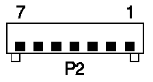
Open the case. Pull out the planar power cable (P1) and the signals cable (P2). Unplug all drives from power cables. Remove the barbed fastener at the top rear of the PSU (black or white). I used a standard screwdriver. At the front of the case you will see the control assembly (power switch). Notice the vertical catch at the bottom center of it? Lift up and out on this latch and the entire control assembly will come out. Now slide the PSU forward until it stops on the front of the case. Pull up. Congratulations. Remove Control Assembly
Remove PSU
Repairing a 35 / 56 /76 PSU (Magnetek,
I bet!)
Now: in most cases there are
Recommendation: try to get some spare PSUs. The IBM models
35, 56 and 76 small desktops use the same PSU (and Mod. 40, 57 and 77 large
desktops use the same larger PSU as well)
>Thanks for the info. It appears that the PSU is made by Delta. The IBM P/N is 79F3367 and the FRU is 79F3443. So hopefully it isn't he PSU if you say that the Delta PSU's aren't known to have a signifigantly high failure rate. The FRU is 79F3443 for all sorts of "Mod. 35/56/76" 118 Watt power supplies, the P/N might differ. The objection on the failure rate however is my own - and derived from a decade with these units from which 90% had the italian Magnetek PSU - and all of them were Greenock/UK productions (serial number starts with 55-). So the statistical number might be invalid, because I did not have too many units under my hands with Non-Magnetek PSUs. But these *are* know for significant high long-term failure rates. While being on it: I have seen a few 9556 with ASTEC / Taiwan PSUs. >As for the delay after power off, I was aware of that, but this problem makes the machine unusalbe for a couple of hours afterwards. [snipped] Then if I come back and power it on a couple of hours later, it runs like normal for only a few minutes. Hmmm. That sounds a lot after a shot / dying PSU. But can be the planar as well. Maybe it is a coincidence, but I have a Mod. 95 with a Delta-PSU. Once you switch it on it takes about 10 - 15 seconds before any light comes on and the fans start to turn. >Out of curiosity, if the PSU was failing, would it get hot or anything like that? Not neccessarily. On the Magnetek-units the failure is basically caused by a too high thermal loss on one or two resistors, which are dimensioned for a loss of 1/8th Watt ... over the years they are "cooked" - get brittle, until they are so much worn that they burn off. A short "pop" - and they're gone. Now the standby-part of the PSU is non-functional (does not supply the sense voltage for the electronic switch any longer) and the main power supply cannot be turned on. Often the failing resistor causes an overvoltage in a Z-Diode - which damages a Thyristor ... which fries some other components ... a little firework. The PSUs used to have a certain "electronic smell" after burned resistors and capacitors. When you disassemble the PSU you will found some parts that turned into coal and a printboard having turned to a dark brownish color in some areas. Sometimes the PSU still works - partially. You can turn it on with unplugging / plugging back the AC-plug ... but the on/off switch is no longer functional. I think yours might be partially damaged, so that the "Power Good" line from the PSU to the planar hangs in "undefined" condition, which holds the Reset line of the CPU low. Therefore the HDs and fans start to spin - but the board does not start up the power on self test (POST) and memory count during that. This -however- could be a symptom of a shot board with a thermal malfunction as well. Therefore my recommendation: try to get a spare PSU to test the unit
with it. It is good to have a spare anyway. Maybe there is someone out
who can lend out one for a test ... ?
Checking the Output- If the power-on indicator is not on, check the power cord for proper installation and continuity. 1.Check for continuity between pins 4 and 6 (switch) on P2.
|
