|
Jumpers
Password-override
jumper (JMP1) Here
on the planar
The power-on password locks the keyboard and mouse (if attached to
the mouse port) to help prevent unauthorized use of your server.
If you are using a mouse that is connected to the serial port, the mouse
remains active.
After you set a power-on password, Enter password appears each time
you turn on the server. Before you can use the server, you must enter
the correct password. (The password does not appear on the screen
as you type it.) When you enter the correct password, Password accepted
appears on the screen, the keyboard and mouse are unlocked, and the system
resumes normal operation. If you type the wrong password, Incorrect
password appears on the screen and Enter password is again displayed.
After three incorrect attempts, you must turn off the server and start
again.
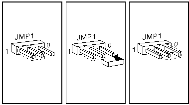 To erase the power-on
password. To erase the power-on
password.
1. Power-off the system.
2. Move jumper to other end.
3. Power-on the system.
The jumper can be left on new position. The password is removed
each time the system is powered-on with the jumper in a new position.
Privileged-access
password jumper (JMP2) Here on planar
Before setting an administrator (also known as privileged-access)
password, it is a good idea to read this section in its entirety.
Using this security feature requires some planning and ongoing administration.
The administrator password allows you to control who has
access to the system programs. If an administrator password is set,
you must enter it to use the system programs in the System Partition on
the hard disk or on the Reference Diskette. The administrator password
also can be used to override the power-on password. After an administrator
password is set, only those who know the password can perform tasks such
as:
o Altering computer settings or features controlled by the system programs
o Running diagnostic tests
o Resetting the system after a forced entry (If the server is forced
open, a POST error occurs. To clear the error, you must enter
the administrator password. Read about the LogicLock)
Your server is shipped with the administrator password
feature Disabled. You must move a jumper on the system board before
an administrator password can be set for the first time. The jumper
has two positions:
o The locked state prevents an administrator password from being set,
changed, or removed. This is the position set at the factory.
o The change state allows an administrator password to be set, changed,
or removed.
Warning: If an administrator password
is set, then forgotten, it cannot be overridden or removed. The system
board must be replaced in order to access the system programs.
The privileged-access password jumper enables setting the privileged-access
password. The jumper has two positions, which are marked on the system
board. The system is shipped with this jumper in position 1, which
prevents the privileged-access password from being set accidentally.
To set the password, move the jumper to position 0 then run Set Privileged-Access
Password in the system utility programs. (The jumper position has no effect
after the password is set.)
Note See Privileged-Access Password
before attempting to set this password.
If the password is removed (using the system utility programs), the
jumper can be returned to position 1 to prevent the password from being
set.
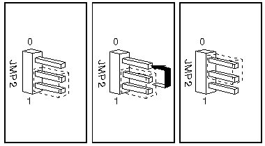
o To set the privileged-access password to
the change state, move the jumper to position 0.
o To set the privileged-access password to
the locked state, move the jumper to position 1.
Cover Interlock
Connector (JMP3) Here
on the planar
A 2- by 3-pin connector connects the cover-interlock switches to the
controlling logic on the system board. The two switches are connected
to the tamper-evident logic.
Switch 1 indicates the position of the keylock to the
tamper-evident logic, and switch 2 indicates when the covers are off.
| Pin |
Signal |
Pin |
Function |
| 1 |
Reserved |
2 |
Reserved |
| 3 |
Switch 2 |
4 |
Detect keylock position |
| 5 |
Switch 1 |
6 |
Detect covers open |
Kickstart
Jumper (JMP4) Here on
the planar
On the Server 95, serial port A can be used to power-on the system
when the power supply is in the standby mode. The kickstart jumper
controls whether the 'serial data in' or the 'ring indicator' signals from
serial port A are used to trigger the power-on sequence. When the jumper
is in position 0, the 'serial data in' signal is logically connected to
the input to the power supply; when the jumper is in position 1, the 'ring
indicator' signal is the source.
Note This jumper should
be set to position 0 for serial connections that do not drive the 'ring
indicator' signal, such as lease line and other directly-connected configurations.
KickStart Jumper Pin Description
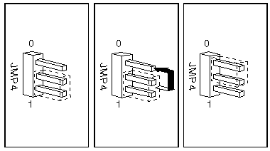
| PIN |
DESCRIPTION |
| 1 |
Serial data in |
| 2 |
Power on request output |
| 3 |
Ring indicator |
- Leased-line state, move jumper to position 0.
- Other modems state, move jumper to position 1.
The Kickstart function is embedded in the Dallas
DS1585S Serialized RTC next to the battery on the 95A planar.
Flash
Memory Bank Selector (JMP5)
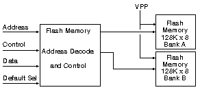
This jumper is on the processor complex and is used to select which
bank of flash memory is accessed as ROM. The ROM subsystem consists of
256KB of flash memory in two banks of 128KB. If the jumper is in position
0 when the system is powered on, bank A is mapped to addresses hex 000E0000
to 000FFFFF and hex FFFE0000 to FFFFFFFF. The system is shipped with
the jumper in position 0 (bank A selected).
Access to ROM or RAM at address space hex 000E0000 to 000FFFFF is controlled
by the bits in the memory controller registers. When ROM is enabled, it
is not parity checked.
If the jumper is in position 1, bank B is mapped to these addresses.
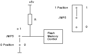 Flash
Memory Bank Select Jumper Flash
Memory Bank Select Jumper
| PIN |
SIGNAL NAME |
POSITION |
| 1 |
Open |
1 |
| 2 |
Select bank B |
N/A |
| 3 |
Ground |
0 |
Note: Do not change the position
of the jumper while the system is powered-on; unpredictable operation will
occur.
Artifact
The "Flash ROM bank" switch -by the way- was originally planned for
a sort of "emergency mode". Once you screwed up the Flash-BIOS you could
toggle the bank, insert any working flash update in the FDD A: and restart
the machine, which takes the flash-image from the floppy drive and recovers
(as it can be done on the 704 in the "Bios recovery mode"). However: the
base boot-BIOS did not have the required routines to delete the loused
up bank of the Flash-ROM ... and as far as I know the loading of an image
from Floppy does not work. Another useless feature.
Remote
Maintenance Service Connector (JMP6)
Here on planar
The system board provides a 2-by-2-pin Berg connector for a remote
maintenance or service adapter, such as the IBM PS/2 ServerGuard
adapter.
When the adapter is installed, the system can be turned off or reset from
a remote location.
When this adapter is not connected to this connector,
a jumper must be in place that connects pins 1 and 2 together for the system
to be powered-on. These two pins provide a signal path to the 'power-on-request'
signal to the power supply.
NOTE: If you get a 95 that's been
stripped, they might have pulled the ServerGuard adapter out, and not jumpered
JMP6. So if your new toy refuses to power up, check this jumper
Remote Maintenance Service Connector
| PIN |
DESCRIPTION |
| 1 |
Power on request input |
| 2 |
Power on request output |
| 3 |
-Reset |
| 4 |
Not connected |
Battery 3v
Lithium
|
Duracell
|
Eveready
|
Panasonic Varta Sanyo
Rayovac Maxell Toshiba
|
AWI
|
NEDA
|
Other
|
|
DL2032
|
ECR2032
|
CR2032
|
L14
|
5004LC
|
EA-2032C
|
PS/2 - 95xx Battery Life Expectancy/Voltage
The battery used on the 95XX products has a normal life
expectancy of five to seven years. The life of the battery is directly
related to how the machine is used. Battery voltage is consumed only when
the system is powered off. Since the battery is a lithium battery, it has
very long shelf life. For correct machine operation the battery voltage
should be between 2.5 volts and 3.7 volts.
To check the battery voltage:
- Turn off the system unit power.
- Remove the battery from the battery holder.
- Check the battery for a voltage of 2.5V - 3.7V DC
If the battery voltage drops below 2.5 volts, it should
be replaced with FRU P/N33F8354. (CR2032) After replacing the battery,
the system unit should be powered on and checked for proper operation.
9595 Main Page
|
 To erase the power-on
password.


 Flash
Memory Bank Select Jumper
