|
DP83257 Datasheet (FDDI Physical Layer Controller) DP83265A BSI-2TM Device (FDDI System Interface) My guess what U9 REALLY is... DP83261AVF BMAC Device (FDDI Media Access Controller) 0826_01.pdf Install Guide for F3019, F3059, F3069, and F3079 FDDI Adapters NP_0112-08 Diags, NW 4.x-3.x ODI,WinNT NDIS 3.0, DOS\OS2 ODI & NDIS 2.0.1 Many thanks to Andreas Kohl for pulling these from the mists of time. NP_mca-lm Enhanced NIF for use with IBM LAN Systems products Note from Andreas: The zip files contains my modification for use with IBM OS/2 networking, simply copy it's content to \IBMCOM\MACS or to a floppy (if you want to test, how LAPS is copying this files). (thanks to Andreas again for writing it!) NP-MCA-3 Base Card MCAPHY-3 DAS Side Card ADF @0069 Sections
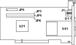
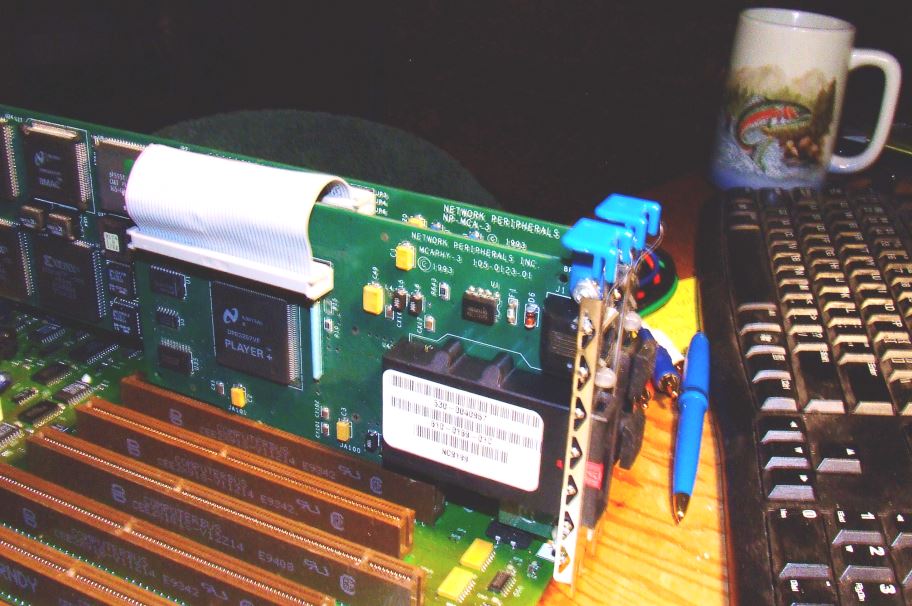
Rightmost pin on JP4 was removed (towards the slot bracket), this assures the 50 pin cable from the side card is attached in only one way. MCAPHY-3 105-0123-01 
JP4 header has rightmost pin snipped. JP5 header has lower left pin snipped. JP6 is only the holes for a row of pins. U21 NS DP83257VF Player + U41 610-0166-01D Transceiver The DAS side card's cables will only fit in the base card if the side card is to the right of the base card. It was easier to put the cables on before trying to put the adapters in the MCA slots because you can have both cards "flat". For us with NP-MCA-3 cards that were banged about some, check the (exposed!) pin header on the base card. Some of the pins may have been bent some, and trying to install the cable will be frustrating.  Gereon Wenzel: Looks like its time to start my work on a FDDI Howto/FAQ? No need someone else already did... Google is your friend! http://www2.rad.com/networks/1995/fddi/fddi.htm http://www.cicese.mx/~aarmenta/frames/redes/fddi/FDDIFAQ.html http://www.cisco.com/univercd/cc/td/doc/cisintwk/ito_doc/fddi.htm > Does anyone have a manual for this card? Not sure if this one matches your cards? http://www.enterasys.com/support/manuals/hardware/0826_01.pdf David Ress IIRC, Win95 has built in support. NT 4.0 has built in support (and auto-detects it, unlike the SK-Net FDDI adapter). Uses Npmca.sys for the driver. I tried a while ago to find the diagnostic program for the adapter and failed. Anyone? NP has since been bought out, and the new company has extremely limited support for NP hardware, mostly switch related. Nothing microchannel. Still, for FDDI networks, it is my preferred adapter. Support for Multi Channel Architecture The BSI-2 device provides three Input Channels and two Output Channels, which are designed to operate independently and concurrently. They are separately configured by the user to manage the reception or transmission of a particular ADF Sections @0069h Network Peripherals FDDI Adapter Map 512 I/O Address Range This selects the 512 I/O address space of the adapter <"5400h thru 55FFh">, 5C00 - 5DFF, 5E00 - 5FFF, 7400 - 75FF, 7600 - 77FF, 7C00 - 7DFF, 7E00 - 7FFF, D400 - D5FF, D600 - D7FF, DC00 - DDFF, DE00 - DFFF, F400 - F5FF, F600 - F7FF, FC00 - FDFF, FE00 - FFFF Modes and Interrupt Level WARNING : DATA STREAMING MODE should be selected ONLY if you are sure that this machine supports data streaming. This will result in better performance. SLOW MODE should be selected if this FDDI adapter is installed in an older Model 80 that has not had the IBM EC applied. (Ed. I think this refers to the non-busmaster capable planars) <"Normal Mode & Interrupt 3">, Normal/Int5, Normal/Int10, Normal/Int15, Data Streaming Mode & Interrupt 3, Data Streaming/Int5, Data Streaming/Int10, Data Streaming/Int15, Slow Mode & Interrupt 3, Slow/Int5, Slow/Int10, Slow/Int15 Arbitration Level Using arbitration levels, this adapter accesses memory directly without burdening the computer's main microprocessor. An arbitration level of 0 has the highest priority, and increasing levels have corresponding decreased priority. <"Level_1">, 0, 2, 3, 4, 5, 6, 7, 8, 9, 10, 11, 12, 13, 14 Map 8K Memory Address Range This selects the 8K memory space of the adapter <"0C0000h thru 0C1FFFh">, 0C2000 - 0C3FFF, 0C4000 - 0C5FFF, 0C6000 - 0C7FFF, 0C8000 - 0C9FFF, 0CA000 - 0CBFFF, 0CC000 - 0CDFFF, 0CE000 - 0CFFFF, 0D0000 - 0D1FFF, 0D2000 - 0D3FFF, 0D4000 - 0D5FFF, 0D6000 - 0D7FFF, 0D8000 - 0D9FFF, 0DA000 - 0DBFFF, 0DC000 - 0DDFFF, 0DE000 - 0DFFFF, 0E0000 - 0E1FFF, 0E2000 - 0E3FFF, 0E4000 - 0E5FFF, 0E6000 - 0E7FFF, 0E8000 - 0E9FFF, 0EA000 - 0EBFFF, 0EC000 - 0EDFFF, 0EE000 - 0EFFFF |
