|
187-082 IBM PC Network Baseband Adapter /A (Wrap Plugs) 187-080 IBM PC Network Adapter II/A (Coax) 187-219 IBM PC Network Adapter II/A-Frequency 2 And 3 (Coax) ADF Sections PC Baseband Adapter 
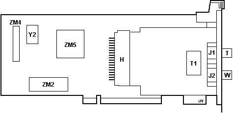
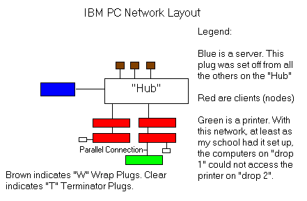
PC Network Baseband Network Layout  William R. Walsh said: It is a "baseband" adapter, whatever that means. Standard RJ11 phone cable and connectors were used to connect the adapters together, and to a "hub" of sorts. The adapters were not only attached to each other (a bus topology), but each "bus" was connected at a central hub, creating a series of connected "subnetworks" at the point of the hub. As for the purpose of T and W plugs, W is identified as being a "Wrap Plug" in my manual, and "T" as a terminator plug. The T plugs were plugged into the second jack of the last adapter on a "line". If you took the "T" plug out of the adapter, the whole line of computers failed to work (like a string of XMAS lights), but other computers on other "subnetworks" would still work. As for the "W" plug, it was put into any of the unused ports on the hub. If it was taken out, the hub would fail to work at all. Also, the hub did not allow communication between clients on two (or more) different "subnetworks" attached to it. This made it necessary to have at least one computer that had a printer on each "subnetwork". The server (if any was used) went into its own special port on the "hub" that could communicate with any of the other connected "subnetworks". As for the insides of the "T" and "W" plugs, it looks
like there is some kind of resistor in the "T" (clear)
plug. The "W" plug has something in it, but I don't know
what it is. Too dark brown to tell for sure. Serial Connection of Baseband adapters "W" plug -- Machine 1 -- "T port" -- "W" port --- Machine 2 -- "T" plug . If using a 5173, the T plug should be on the card farthest from the 5173. The W plug should be in either one of the 5173's OUT ports. Think of it like terminating a SCSI chain. Up to eight systems can be serially connected. Maximum distance from first to last nodes # Nodes Max Distance 2 91.4m (300 ft) 3 83.8m (276 ft) 4 76.0m (250 ft) 5 or 6 68.5m (225 ft) 7 or 8 61.0m (200 ft)
IBM PC NETWORK-BROADBAND IBM's broadband PC Network addresses the specialized requirements of customers who are combining their LAN with other services, such as video, voice, security and/or additional data channels on a common broadband medium. It may also be used to meet the requirements of small businesses and individual work groups. IBM PC NETWORK ADAPTER II: The IBM PC Network Adapter II is a feature card for connecting the new IBM Personal System/2 Model 30 and IBM Personal Computers to the broadband IBM PC Network. It is compatible with the form factor and bus design of the original Personal Computer, yet it is designed to take advantage of greater Intel 80286 and 8086 processing speeds. The IBM PC Network Adapter II supports the NETBIOS interface and the 802.2/Logical Link Control (LLC) protocols via the IBM LAN Support Program which was also announced today. This allows the adapter to provide access to IBM PC Network and IBM Token-Ring Network applications written to the NETBIOS or APPC/PC interfaces. The IBM PC Network Adapter II is also compatible with the protocols of the original PC Network Adapter via the IBM PC Network Protocol Driver program which was also announced today. This allows the adapter to take advantage of the same protocol and interface as the original IBM PC Network. See IBM Product Announcement 187-079, dated April 2, 1987, for details. IBM PC NETWORK
ADAPTER II/A: The IBM PC Network Adapter II /A
is a feature card specifically designed for connecting
the new IBM Personal System/2 Model 50, Model 60, Model
80-041, and Model 80-071 computers to the broadband IBM
PC Network. It is compatible with the form factor and
bus design of these new Personal System/2s to take
Channel usage, frequencies, offsets, and splits
PC Network Broadband 
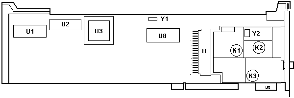
I have a similar card that has the module
used in the broadband adapter above. Possibly this
card/module combination could be used as a baseband or
broadband with the swapping of the module. The slot
cover and module are attached to the base card with two
screws. To swap the module, you unscrew both screws on
the back of the base card and then screw on the new
module after plugging it in the socket. Broadband Adapter Compatibility Direct communication between PC Network adapters is possible only when each adapter uses the same RF channels and the same protocols. The PC Network Adapters (original, II, and II/A), the IBM PC NETWORK ADAPTER II/A - FREQUENCY 2 and the IBM PC NETWORK ADAPTER II/A - FREQUENCY 3 cannot communicate directly with each other. For communication between different RF channel pairs, bridging is required. Broadband PC Network adapters can communicate with each other according to the table below: | # | = Direct communication supported when both adapters are using PC LAN Support Program (802.2 protocols). | | = Bridging required for communication. 1 2 3 4 5 6 7 |---+---+---+---+---+---+---| - IBM PC Network Adapter | # | # | # | | | | | |---+---+---+---+---+---+---| - IBM PC Network Adapter II | # | # | # | | | | | |---+---+---+---+---+---+---| - IBM PC Network Adapter II/A | # | # | # | | | | | |---+---+---+---+---+---+---| - IBM PC NETWORK | | | | | | | | ADAPTER II - FREQUENCY 2 | | | | # | # | | | |---------------------------| - IBM PC NETWORK | | | | | | | | ADAPTER II/A - FREQUENCY 2 | | | | # | # | | | |---+---+---+---+---+---+---| - IBM PC NETWORK | | | | | | | | ADAPTER II - FREQUENCY 3 | | | | | | # | # | |---+---+---+---+---+---+---| - IBM PC NETWORK | | | | | | | | ADAPTER II/A - FREQUENCY 3 | | | | | | # | # | |---+---+---+---+---+---+---| NOTE
Adapters that use unlike protocols can coexist with each
other on the same coaxial cable, but will not be
able to communicate with each other.
AdapterId EFEF "PC Network Adapter " Type, Memory Location,
Interrupt Level |