|
This page is based on Peter Wendt's original HERE
. I have done some minor editing for [hopefully!] better readability. All
errors are my problem... I do this to save the future MCA Addicts from
having to find this link years from now. I hope.
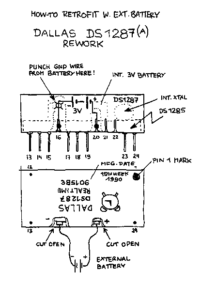
Peter of Lemgo spake thusly: You have either a PS/2 25-286, 30-286, 55 or 65 which comes up with a "165 configuration error" and fail to keep the setup once been shut off again. Well - these have the dreaded Dallas DS1287 "all in one" Real Time Clock (RTC) chip with integrated Xtal and battery. Now the battery is dead, configuration is lost after relatively short time again and you get error-codes constantly. A really new, fresh and unused chip is hard to get. Even its successor DS12887 is pretty hard to get and darn expensive. At that point you wish you could add an external battery. But you can't. There are no provisions for one. Not yet. The Action: Have a look at the graphics below. Basically the DS1287 is a DS1285 chip, where the pins for the xtal-connection and the battery are bent upwards. Then the battery and xtal are placed atop of the chip, connected to the pins and everything is covered with a pretty rigid protective compound. 
What you need to do: * use a Dremel or a metal saw to cut at pin 16 vertically down to the metal pin surface * repeat the procedure at pin 20 * scratch off the sealing compound around the pins, particularly at Pin 16 towards the top * use a watchmaker screwdriver or a nail to break the connection to battery minus over pin 16 NOTE: Don't be afraid: this chip is really hard to damage. If you have a multimeter test the voltage on pins 16 and 20 before and after. Before it may read anything from some 100mV up to 3V (where you should ask yourself *why* you wish to modify this chip ...?) and after it must be 0 (zero) latest after 5 seconds of measuring. When you get a 0V-reading, you have successfully disconnected the battery.
NOTES:
This abstract "3 Volt Cell" could be either a battery pack [2 AA or AAA]
or a 3V-Lithium coin cell - with holder !
* maybe use some
hot glue to re-isolate the pins and fix the battery somewhere on the chip
* Re-install the reworked chip in the machine - watch out for proper aligment and position of pin 1 - and reconfigure your PS/2 with its reference diskette. Should work like a charm. |