NEC Multisync Graphics Engine
@0F5F.adf NEC Multisync Graphics
Engine
@0F5F.ADF (Eizo
version, rename to @0F5F.ADF)
Option Disk for NEC MGE
MGE
General Specs
Directory
All This is From (Drivers, TIGA software here too..)
NEC MGE / Eizo GC-40
ADF Sections
Multisync Graphics Engine
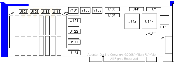
(Image and text in section from William Walsh HERE)

JP1 - Connector for memory daughtercard
JP2 - Connector for memory daughtercard
JP3 - Unknown, open on my adapter.
P1 - Video Output (VGA connector)
Y101 - 36.0000MHz XTAL (for 640x480)
Y102 - 50.0000MHz XTAL (for 800x600)
Y103 - 64.0000MHz XTAL (for 1024x768)
U103-118 (four ICs) - NEC 424256-10
U121 - REF-02
U122 - BUF-02 |
U123 - CAS-02
U124 - DEC-02
U133 - BLNK-02
U134 - BUSARB-02
U141 - STATE-12
U? - SLAV-02
U142 - TI TMS34010FNL-50
U147 - Chips P82C611 MCA Bus Interface
U150 - Brooktree BT471 RAMDAC
0 |
JP3 - Open on my adapter. NEC says
to remove this jumper if monitor displays with a green hue.
Between JP1 and 2 lies the adapter's main video memory section. The
chips here are soldered NEC D41264C-12. I believe they represent the base
512K of VRAM.
What is the purpose of the resistor networks above U121-U124? Why are
they socketed?
Note that the resistors are socketed with one hole left empty on the
board mounted socket. If you need to replace them, be sure the leftmost
position of the socket (with P1 facing RIGHT) is not populated.
This adapter does not provide its own base video. You'll need another
card or onboard video for that.
Windows 95 Support
From the NEC Win95 FAQ:
Q: I plan to install Windows 95 on my PC. Will I be able to get new
drivers for my NEC MGE-AT Graphics Card?
A: Since this line of video cards have been out of production for a
number of years, NEC does not plan to develop Win 95 drivers for the MGE-AT
video cards.
Warning, folks! 256 colors MAX! (even with the memory
upgrade). I have one with documents... Save your money..Strictly a CAD
card..
MGE-MCA 16 - Displays 16 colors in Hi res. It will
default in boot-up mode to standard 640 by 480 analog VGA, and also offers
hi resolution modes of 800 by 600 and 1024 by 768 for software that is
supported via device drivers.
Resolutions: 640x480, 800x600, 1024x768 both I/NI
Memory Map: VGA - A000 - C7FF I/O 0x3C6 - 0x3C9
Hi Res - I/O 0x1CC - 0x1CF 0x1D0 - 0x1D8
Upgrade from 16 to 256 color with MGE-4A daughter board
Power Consumption: MGE-AT 16 - 16 Watts
@ +5 Volts (54.608 BTU/Hr)
| Pin |
Signal |
Pin |
Signal |
| 1 |
Red |
9 |
N/C |
| 2 |
Green |
10 |
Ground |
| 3 |
Blue |
11 |
Ground |
| 4 |
Ground |
12 |
N/C |
| 5 |
Ground |
13 |
H Sync |
| 6 |
Red Gnd |
14 |
V Sync |
| 7 |
Blue Gnd |
15 |
N/C |
| 8 |
Green Gnd |
|
|
ADF Sections 0F5F
"Multisync Graphics Engine"
Enable/Disable Adapter
Use the Enabled setting for normal use and disabled
if you are not using the adapter and enabling it causes a conflict with
another device.
<" Adapter Enabled " >
, Adapter Disabled
Hardware Registers
The range of i/o addresses used. These include the 34010
host port registers and the
command and status registers. These addresses cannot be used
by another installed device.
<" BC0 to BCF ">,
7C0 to 7CF, FC0 to FCF, 13C0 to 13CF, 17C0 to 17CF, 1BC0 to 1BCF, 1FC0
to 1FCF
Color Palette addresses
Color palette I/O addresses. If mapped to 3C6-3C9, it
shadows the VGA color palette
<" 3C6 to 3C9 ">,
7C6 to 7C9, BC6 to BC9, FC6 to FC9, 13C6 to 13C9, 17C6 to 17C9, 1BC6 to
1BC9, 1FC6 to 1FC9
Interrupt Level
<" Channel 9 ">,
10, 11, 12
Pixel Clock Frequency
64 Mhz provides 1024 x 768, 50 Mhz provides 800 x 600,
36 MHz provides 640x480
<" 50 Mhz ">,
64 Mhz, 36 Mhz
Bus Arbitration Level
Determines the bus arbitration level for the 34010 bus
master.
<"Level 7">, 3,
1, 5
Horizontal Sync Polarity
Sets the horizontal composite sync polarity for high resolution
graphics modes.
< Negative ">,
Positive
9595
Main Page
|
