|
Open the Case How to fix a "Broken" Door Plasma Display Information VGA, CGA and EGA resolutions Color graphics contrast Text mode contrast Auto-dim feature External PS/2 displays Color to Gray Mapping Turned-on Display Plasma Display Brightness Close Plasma Display Why does Plasma Display Get So Hot? "Cool" Windows Color Schemes Plasma PCB Remove Hard Drive Miniture Right Angle KB Plug Identity Minature KB Connector Pinout External Storage Device Port External Storage Device Cable ESD Cable Pinout ESD Cable Hosiden Connector Pinout Cable Source Remove power On Password Jim Shorney's "The P70 Project" (P70 and P75 Stuff) Locate the Type-Model 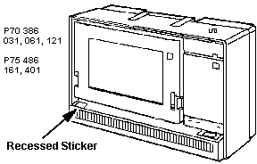
Opening the Case
NOTE: There are two additional
catches, one to each side of the carrying handle.When you lift up the rear
cover, it pivots on them. How to Fix a "Broken" Door From Us, the god-Emperor of Microchannel How many times have you seen the ports cover hanging loose off of a P70 or P75? Chances are, it ain't broke, just discomboobulated. Open the case. (unscrew the three captive screws, pry out and up on the bottom edge). Pull up on the bottom edge and rotate it up on the pivots at the top rear of the case. Look at the slots where the ports door hinges enter the case body. See the wide end? If you look on the interior of the case on the opposite of the wide ends, you will notice a pivot point for the metal hinge to fit into. Remove the ports cover by pressing the hinge inwards (relative to the port cover). Look at the "U" shaped arms of the hinge. Are they straight out from the metal strip? They should be at right angles to the metal strip. If they aren't, _carefully_ bend them so they are. Now reinsert the hinges through their slots and pop the hinge points back into the matching pivots. You may have to carefully press the hinges inwards, since the pivots have a lip around them. Shut door. If the hinges want to pop free, carefully bend them outwards just
a little more, so more force is exerted against the pivots, Plasma Display Information The computer has a gas plasma display that shows program colors in up to 16-level monochrome shades with a VGA of 640 X 480 resolution. Some programs may not be designed to take full advantage of the plasma display, or could benefit from minor changes. Here are some tips for best results. CGA and
EGA resolutions-Programs using CGA and EGA resolutions are supported
by this display; however, program screens will not use the entire plasma
display area, and graphics shapes could be slightly distorted. How much area
of the plasma display is used by VGA, CGA, and EGA is illustrated in the
figure below. For best results, use the version of a program that supports
VGA resolution. Color
graphics contrast-The plasma display automatically converts program
colors into different monochrome shades. Some programs start with colors that
lose contrast when converted. You can usually change colors from within the
program to help increase the contrast. A program will not start; parts of a program screen are missing-Some graphics programs, for example, Microsoft Windows i386 versions 2.1 and below, may not recognize the graphics capabilities of the plasma display and other PS/2 monochrome displays. This could appear as start-up difficulty, or faded/missing information. To correct this situation, put the plasma display (or the attached PS/2 monochrome display) in graphics mode before starting the program. To do this, type MODE CO80 at the DOS prompt, then press Enter. Text mode contrast-The contrast in text (non-graphics) programs is best when the plasma display is in two-shade text mode. The display is in this mode when the computer is turned on, but could be put into graphics mode by a program. To return the display to text mode, type MODE MONO at the DOS prompt, then press Enter. Auto-dim feature-The plasma display is automatically turned off to extend its life if no data is received from the system or entered from the keyboard or an auxiliary device for 10 minutes (default value). The default value can be changed by using the backup copy of the Reference Diskette. To change the default value, go to the Auto-Dim Time. The following shows the path to the Auto-Dim Time. Main Menu>Set Configuration>Change Configuration>Auto-Dim Time There are two ways to turn on the display again: If the mouse picks up vibration from a desk which turns on the display again, change the Auto-Dim Reset from Keyboard and Aux. Device to Keyboard Only. The following shows the path to the Auto-Dim Reset. Main Menu>Set Configuration>Change Configuration>Auto-Dim Reset External PS/2 displays-The computer supports all PS/2 displays with VGA resolution. If you use the same program with the plasma display or an external PS/2 display, the best choice for program colors could change depending on the display you are using. Color to Gray Mapping-There are some applications that are developed for color displays but can be used on monochrome displays. When using such applications, reset the Color to Gray Mapping to Green Signal Only. Setting RGB Mixed Signals (default value) may result in an unpredictable display image. The following shows the path to the Color to Gray Mapping. Main Menu>Set Configuration>Change Config>Color to Grey Remapping Turned-on
Display-The default value, Primary, turns on only one display that
is considered by the system to be the primary display. When no external PS/2
display is connected to the system unit, the plasma display is considered
the primary display and only VGA mode is supported. But when an external PS/2
Main Menu>Set Configuration>Change Config>Turned-on
Display Plasma Display Brightness You can reverse the brightness of standard text and emphasized text in DOS through a simple command, BRT. This command lets you set standard text brighter than emphasized text, or vice versa. The Reference Diskette contains this command program and a program to install it. When you attach an external PS/2 display or use certain programs, the brightness is not selectable. That is, emphasized text is always displayed with brighter characters. How to Install the Brightness Program
After Installing the brightness program, use the following instructions on how to change the brightness level. To Change the Brightness Level
Close Plasma Display 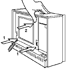
First push back the lower edges into the case. Now push the upper
edges back into the case. Seems odd, but it works. Why
does the screen on the P7x get so hot? "COOL"
Windows Desktops Plasma Control PCB M480L640HB53 (single row connector plasma screen) 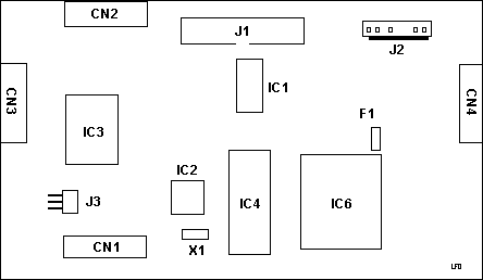
Hard Drive Removal
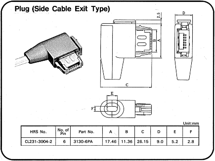
KB Plug Identity The P7x right angle connector is HRS # CL231-3004-2, part # 3130A-6PA Go to the Hirose Electric web page and look at their catalog HERE T. Sunagawa sez:
27 Nov 01- Trying to convert between the four pin header and the common PS/2 port. My urge is to allow installing a short female PS/2 plug to stick an external PS/2 keyboard on. You might even want to create your own extension cable, because finding the special extension cable is about as likely as finding Elvis in your kitchen. David Beem wrote: Pin 2 = +5VDC (Red on mainboard connector) Still trying to get an "M" apart for cross-comparison.
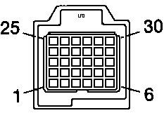
External Storage Device Port The external storage device port is the equivalent of the B drive internal diskette port, as found in the PS/2 Model 70. This permits attachment of externally powered devices like the IBM 4869 External Diskette Drive Model 001 and some other equipment manufacturers' backup devices.
1 N/A Ground 2 I - Second Drive Installed 3 N/A Ground 4 O - Reduced Write Current 5 N/A Ground 6 N/A Reserved 7 N/A Ground 8 I - Index 9 O - Motor On 1 10 O - Drive Select 1 11 N/A Reserved 12 N/A Reserved 13 N/A Ground 14 O - Direction 15 N/A Ground 16 O - Step 17 N/A Ground 18 O - Write Data 19 N/A Ground 20 O - Write Gate 21 N/A Ground 22 I - Track 00 23 N/A Ground 24 I - Write Protect 25 N/A Ground 26 I - Read Data 27 N/A Ground 28 O - Side 1 Select 29 N/A Ground 30 I - Diskette Change NOTE: NC means No Connector, there is nothing in the socket. External
Storage Device Cable External Storage
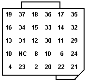
Device Cable Pinout Hosiden Connector
to 37 pin Connector Pinout NOTES: External
Storage Device Cable Source
P70 Trivia (applies to P75 some) The system I am using sometimes refuses to start after power-on without any display or beep symptom. After several power on-off eventually it starts. Any idea??? From Peter On various occasions I saw failing mainboards. They refused to come on - and I don't know why. They simply died from one day to the next and could only be replaced. Back in the "good old days" with full IBM support and machines under warranty that was no big problem. Today things look different. If cleaning the power supply doesn't help - and if removing all adapters and testing with the bare sysboard doesn't change the misbehaviour: suspect the mainboard to be damaged and look for a replacement. Under rare circumstances a poorly seated card-riserboard caused trouble. Have the small two-slot riserboard removed, clean the contacts and spray a good amount of TV-tuner cleaner in the board connector. Let it dry for 10 minutes and use a piece of stiff card pushed into the connector with one edge and move it up / down the connector. Then spray the connector once again and let it dry for an hour. You might also repeat these steps on the two MCA slots on the riserboard. Especially on the slot pointing towards the top of the unit, which collects dust when left with no card installed for a longer time. Some older units also developed a sort of "creeping short" along the FDD cable where the FDD cable enters the "flip out" FDD bay. There was an ECA for the FDD cable from IBM for the earlier models, where FDD cables broke, shortened DC-voltages to GND or FDD signals and caused a dead systemboard. (Few only - IBM fixed it in an early stage). Another potential problem has been reported with the memory modules. The system takes only 1 and 2MB modules anyway, but certain 2MB modules installed on the sysboard connectors with double sided 10 chips layout (20 chips total - 2 x 8 data + 2 x 2 parity - 16 bigger and 4 smaller chips) caused overload of the memory driver lines. This usually resulted in either a 200-something memory error -or- a machine failing to come up at all. I take from the 16MB you'd mentioned that the upper slot contains a memory card (the lower is too short anyway). So you should probably check the card connector as described further above and check if you cannot use memory modules with lower amount of chips. Usually the memory installed on cards causes a 200-series memory error in first place before dumping the machine to total darkness - but you never know. I have several P70 in my collection and all of these run with double-sided
2MB chips ... but I had a customer machine in '93 or so, which didn't. We
used later 2MB/70ns 9-chip modules "hardware-recoded" (with soldering) to
2MB / 85ns and the system worked like a charm. Remove Power-on Password (P75 shown, P70 similar) 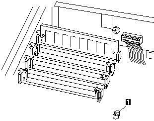
To remove an active, unknown, power-on password do the following. 1. Power-off the computer and unplug the power cord. 2. Remove the system-unit cover. 3. Short the two pins of JP1 together. With the pins shorted, power-on the computer. This erases the power-on
password. Remove the short after POST is finished. |
