|
EZDOS322
EZ-Tape V3.22 DOS Backup Software Thanks to Niels C. Grønlund
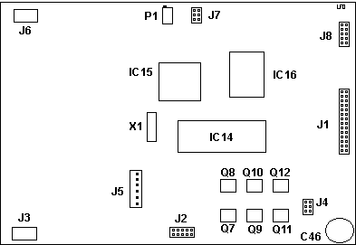
ITBU Main PCB
ITBU Main PCB 4302005 
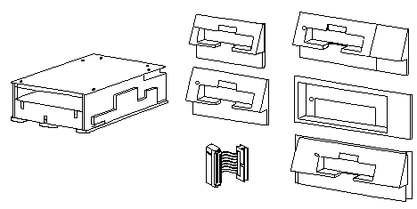
ITBU Frame
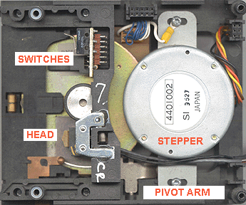
Note the two switches at the upper right. I believe that they are for write enable and tape capacity.

J8 Pinout  Look at the rear of the
drive with the edgecard on the right. Look at the rear of the
drive with the edgecard on the right.
> What is the purpose of the 10 pin header J8 to the immediate left of the edgecard? It has a two wire jumper on the second pin pair from the edgecard. Rick Ekblaw reaches way up and snags it with:
You might wonder why card edge pins 10 and 6 would be used
for drive selection, since they are not listed as drive selects.
I suspect that the manufacturer of the IBM ITBU (Irwin) used the drive
selection pinout of the Sony 34-pin floppy interface (where pins 10, 12,
14 and 6 correspond with drive selects 0, 1, 2 and 3), and since the ITBU
was only intended to work with drive select 1, nobody paid attention to
the other pins. The ITBU is similar in design to the Irwin Accutrak
A250, but they are not the same drive (the A250 is used in IBM PC/AT compatible
designs, the ITBU is designed to work with IBM PS/2 logic levels).
The ITBU is supported by the Irwin EZ-TAPE software.
IBM PS/2 INTERNAL TAPE INSTALLED IN 95XX Record number: H12308 Customers that have installed a IBM Internal tape drive in the following machines 9557
And are having trouble using thir tape drive. Check to see if the tape drive is connected to the third berg connector (usually the nearest connector to the motherboard). This cable will usually have a mark on the connector with the following labels:
P2-2
The Customer's tape drive generally will be connected to
the second berg, but to be correct it should be installed in the 3rd connector
and the 3rd drive bay of these boxes 9577, 9557.
**PS/2's that have 3 berg connectors on them could also be 8590 and 8595. NOTE: In the case of machines running 4680 OS, the
2nd connector of the cable should be used. Keep in mind that DIAGNOSTICS
MAY FAIL WHEN THE TAPE DRIVE IS ATTACHED TO THE 2ND DROP.
ITBU Use on Later Systems >I have never been able to get the PS2-Tape working on 9595 type 4 complex. No problems on an 8595 or a scsi MB 77. Peter utters:
The IBM PS/2 Internal Tape Backup Unit is an internally mounted product that performs fixed disk backup and restore for the following IBM PS/2 products. 8525, 30, 50, 55, 60, 65, 70, 80, 9556, 57, 76, 77 The unit allows the user to transfer up to 80MB or 120MB of data from a fixed disk to a removable tape cartridge. The tape drive slides into the Diskette Drive B slot in the PS/2. The ITBU uses a 3.5" mini tape cartridge for operation. The following
cartridges are supported:
The tape unit requires the IBM PS/2 ITBU Backup program for operation. This program is not provided with this option. (PCTOOLS V-7.x and other Utilities) Accelerator Cards Irwin 4100MC 1-Mbit (MCA) ADF Sections
for 4100MC
HIGHLIGHTS o Supports Models 50, 60, 70, and 80 o Up to 80Mb storage capacity o Supports data interchange between PS/2 Models 50, 60, 70, or 80 o Internal unit 3.25" form factor o Slides into existing diskette controller (Drive B position) o Accurate head positioning using closed-loop embedded servo o Uses 1/4" tape mini-cartridges o Backup rate approximately 2Mb/minute. EXTENDED LENGTH MINI TAPE CARTRIDGES:
Installing the Tape Unit
Cleaning the Tape Unit Read/Write Head
ITBU AIX Drivers >Can aix 1.2 talk to the internal tape unit? That's the one that sits in the second drive bay on a model 70. If so, what device does it respond to? Harry Haas
The driver works fairly well, but you cannot mount the drive, only backup
and restore to/from it. Also the documentation on the RPQ is vertually
non-existant. You have to read through the file:
Jerry Queirolo
PS/2
ITBU and '/etc/backup' inefficiency
It turns out that the 'backup' program (when invoked with -f/dev/rst0) defaults to a tape density (d) of 700 bytes per inch and a tape length(s) of 4500 feet. That works out to a limit of 36,000 1K blocks per tape cartridge. In other words, 'backup' does not automatically determine the type of cartridge installed and write an amount of data appropriate to the installed cartridge. The documentation tells us we CAN'T change the density parameter or the tape length parameter when used with the ITBU. This morning I tried playing around with the -d and -s parameters and I can now say that the documentation is wrong. It is possible to tweak these values and have 'backup' use much more of the tape cartridges. There are several known facts: The ITBU hardware uses 32 data tracks.
A little on the conservative side, I want 'backup' to use only 75 MB of a DC2080 tape and 115 MB of a DC2120 tape (to allow for bad blocks which should be formatted out). So ... Total Capacity = tape density * tape length * 12 tape density = Total Capacity / (tape length * 12)
The tape density is the same for both DC2080 and DC2120 tapes, the increased capacity is due only to the increased tape length. - - - - - - - - - - Cut here for future reference - - - - - - - - -
- -
find . -print ! /etc/backup -s 6560 -d 1000 -i -v -f/dev/rst0 For DC2120 tapes: find . -print ! /etc/backup -s 9840 -d 1000 -i -v -f/dev/rst0 - - - - - - - - - - - - - - - - - - - - - - - - - - - - - - - - - -
- -
Diskette Drive 34-Pin to ITBU 40-Pin Connector (Adapter Cable) From Bob Eager's Tavi PS/2 pages The page for the pinouts is HERE There is an adaptor cable that connects the 40 pin card edge connector to the newer 34 pin header connector. It is used (for example) when installing the Internal Tape Backup Unit (ITBU) or the External Diskette Drive adaptor (the dummy drive cage) to machines that do not use the edge connector interface. It might also be useful in extremis if it were necessary to fit an older drive to one of the newer Model 80s (the actual drive retention cage is the same). The IBM version of this cable uses about 3cm of 34 way ribbon cable, with the (female) edge connector on one end and a (male) header connector on the other. However, wiring is not 'straight through'; the power connections differ between the two interfaces. Ed. Dalco has 40 Pin IDE Edgecard Connector $ 0.30 go HERE NOTE: This goes to a header on a Model 80, and I would heartily recommend checking the pinout for the 40 or 44 pin header used on the later systems BEFORE you wire this up... Edge conn pin Header
conn pin Signal
In practice, manufacture of this cable is fairly straightforward. Cut a short piece of 34 way ribbon cable (about 6cm). Fit the 34 way header connector in the normal way, remembering that the edge with the red stripe goes to pin 1. Separate out wires 3 and 6 for most of the length of the cable, leaving about 1cm intact nearest the header connector. Cut the three main parts of the cable (wires 1-2, 4-5, and 7-34) back to about 3cm in length. Trail wires 3 and 6 across the surface of the rest, and hold temporarily in place with a small piece of sticky tape. Fit the edge connector loosely, making sure that the wires all go in the right connectors (a gap of one wire between each of the first three sections, counting from pin 1, a 3 wire gap to the single wire from pin 3 on the header, and a 1 wire gap between that and the final wire (from pin 6 on the header). When all is in place, crimp it all home. It may be worth winding some wide tape round the cable, transversely,
to avoid the two single wires snagging on something when the cable is fitted.
> Is there a utility for formatting rhomat tapes of 120 meg? I haveformatted many of the 80 meg but my utility doesn't include 120 meg and they show only 80 meg when using that utility. Bob Eager sez
> The 2120 will work; so will the 2080. However, it needs to be the Rhomat format with special servo tracks. Either get Rhomat format tapes, or get truly blank tapes and format them (takes 2-3 hours). Just to expound on that last point a bit: When Bob says "truly blank", he means it. I had received a small herd (30 to 40) of DC2120 Ximat tapes that I wanted to reformat and use in the ITBU. Since I have a Taberaser 409 available to me at work (a 40-plus pound monster of a tape degausser, intended to work with reel tapes, including the old wide reel-to-reel video tapes), I figured that erasing the DC2120 tapes would be easy. Each one I tried would start running the format procedure, and fail after an hour or so. Then I got the word that they had to be *really* erased to reformat to Rhomat. So I took the tapes back to the Taberaser, placed them metal side up, and hit each one with 4 erase cycles. Every single tape then formatted properly (running PMTAPE under OS/2, of course, but I would expect that the DOS version of the ITBU tape program would work as well). Rick Ekblaw
@707E.ADF Irwin 4100MC Controller I/O Addresses
Interrupt Request Level
Arbitration Level
Fairness On/Off
|
