Home 

IBM 5150/5160  -  Some IBM Expansion Cards and Options

IBM Printer Adapter
IBM Asynchronous Communications Adapter
IBM Serial/Parallel Adapter
IBM Game Control Adapter
IBM 5.25" Diskette Drive Adapter
IBM 32KB Memory Expansion Option
IBM 64KB Memory Expansion Option
IBM 64/256KB Memory Expansion Option
IBM 256KB Memory Expansion Option
IBM 2MB Expanded Memory Adapter
IBM Fixed Disk Adapter
IBM Monochrome Display and Printer Adapter (MDA)
IBM Color/Graphics Monitor Adapter (CGA)
IBM Enhanced Graphics Adapter (EGA)
IBM Professional Graphics Controller (PGC)
IBM PS/2 Display Adapter (IBM Display Adapter)
IBM Personal Computer Keylock Option
IBM PC Music Feature
IBM Personal Computer Internal Modem 1200


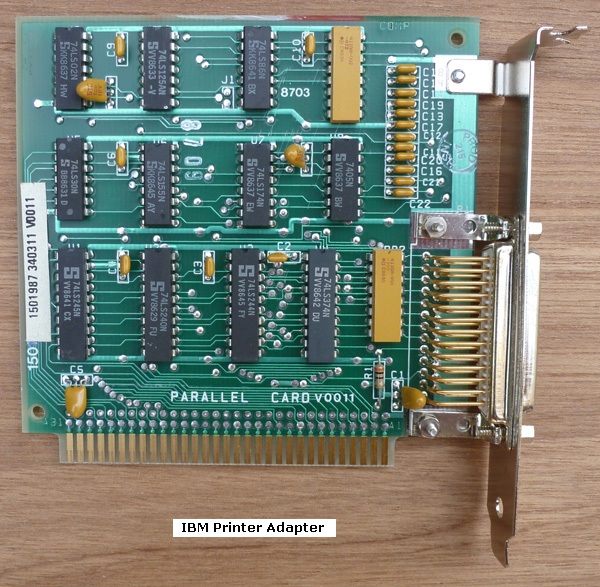
IBM Printer Adapter

This card provides one parallel port.  It is what later became referred to as a 'standard parallel port' (SPP) - see here.

The port is hardwired to I/O base address 378, and interrupt 7.
Only one of these cards may be fitted in the IBM 5150 or 5160, and can only be fitted if the computer doesn't already have a parallel port at I/O base address 378.

This card will co-exist with the parallel port in an 'IBM Monochrome Display and Printer Adapter' card (MDA).  More info.

Click here to see IBM's technical document for the card.


5150_5160_printer_adapter.jpg Click on photo for larger view


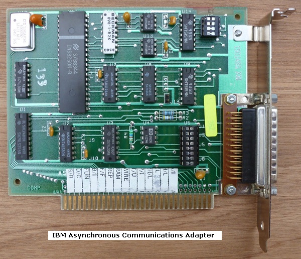
IBM Asynchronous Communications Adapter

This card provides one serial port, specifically a serial port of type RS-232.

The shunt block at the top-right corner controls whether the card is the 'primary adapter' or the 'alternate adapter'.
'Primary adapter' corresponds to I/O base address 3F8 and interrupt 4.
'Alternate adapter' corresponds to I/O base address 2F8 and interrupt 3.

Of those, what you would set depends on what existing serial ports exist in the computer.
If this card is the only serial port in the computer, then you would set this card to 'primary adapter'.
If the computer already has a serial port at I/O base address 3F8, and none at 2F8, then you would set this card to 'alternate adapter'.

Jumper block J13 would have been added to this card at about the time of introduction of the IBM 5160.  Per IBM's technical document for the card, J13 needs to be jumpered if this card is fitted to slot 8 in an IBM 5160  (or IBM 5155).

Click here to see IBM's technical document for the pictured card.
Click here to see a very early version of the card, one that has no shunt block.


5150_5160_serial_adapter.jpg Click on photo for larger view


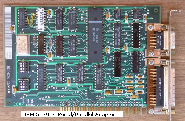
IBM Serial/Parallel Adapter

Combined serial port (of type RS232) and parallel port on one card.

Released with the IBM 5170, but can be used in the IBM 5150 and IBM 5160.

Up to two of these cards (configured appropriately) may be fitted in the 5150/5160.

The printer port is what later became referred to as a 'standard parallel port' (SPP) - see here.

Click here to see IBM's technical document for the card.
There is an error in that documentation in regard to the setting of jumper J2 - parallel port address/interrupt.
That error is on document page 20, where "Port 1" has been labelled as "Port 2", and vice-versa.
Accordingly, the first one of these cards in your 5170 should be configured per the photo below (Serial port 1 / Parallel port 1).

A serial port configuration of 'Port 1' corresponds to: I/O base address (port) of 3F8, and interrupt 4.
A serial port configuration of 'Port 2' corresponds to: I/O base address (port) of 2F8, and interrupt 3.

A parallel port configuration of 'Port 1' corresponds to: I/O base address (port) of 378, and interrupt 7.
A parallel port configuration of 'Port 2' corresponds to: I/O base address (port) of 278, and interrupt 5.


5170_serial_parallel_adapter_s.jpg Click on photo for larger view


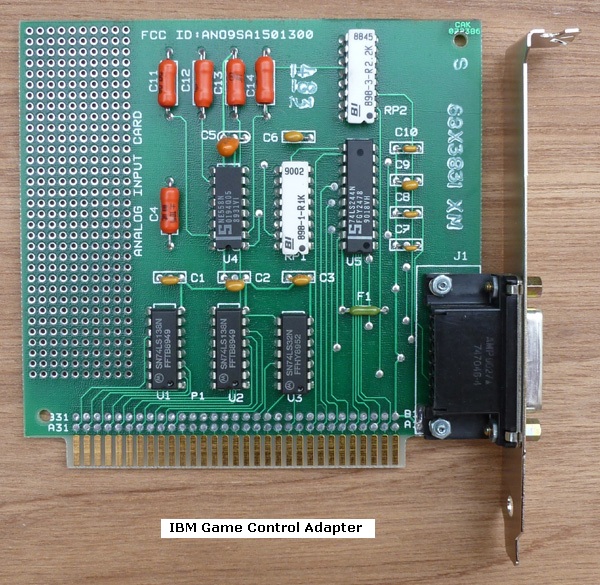
IBM Game Control Adapter

This card provides one game port.
Only one of these cards may be fitted in the IBM 5150 or 5160.

Note the 'ANALOG INPUT CARD' printed on the card, together with the hole matrix for additional components.  Clearly, IBM were catering for engineers who wanted to use the card for a purpose other than a game port.

Note the fuse, 'F1'.

Click here to see IBM's technical document for the card.

The IBM part number for the card is 1501300


5150_5160_game_adapter.jpg Click on photo for larger view


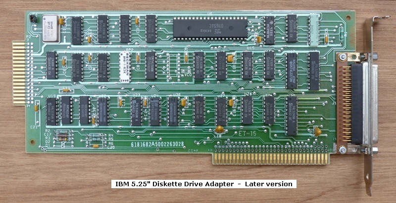
IBM 5.25" Diskette Drive Adapter

Only one of these cards may be fitted in the IBM 5150 or 5160.

Supports up to 4 drives: 2 internal, and 2 external.  Diagram at here.

This is a double density (DD)(2D) controller, intended for 180K and 360K floppy drives.

1.2M drives are not supported.  Click here for more information.

A 1.44M diskette drive connected to this card will not work at 1.44M capacity (due to lack of 500 KBPS data rate support on the card), but will work with 720K diskettes.  Click here for more information.

The jumper on P3 of the later version of the card, is a 'factory use only' jumper.  Leave it on.  (Technical: Connects/disconnects the adjacent 16 MHz oscillator).
The early version of the card has no jumper on P3.

This card does NOT provide power on its external connector (J1).

Click here for cabling information.
Click here to see IBM's technical document for the card.
Click here to see an early version of the card.


5150_later_diskette_adapter.jpg Click on photo for larger view


IBM 32KB Memory Expansion Option

This card provides 32 KB of conventional memory, via 2 banks of 16 KB.

RAM chips of type 4116 are used, of an access time rating of 200 ns (or faster).   4116 examples.

The switches control the starting address of the RAM.  Click here to see the settings.

The circuit diagram of this card is in appendix D of the AUG81 edition of the IBM 5150 Technical Reference manual.  (Link to manual here.)

I have no photo of this card.  The card is known to have "32KB MEM. CD." printed on it.


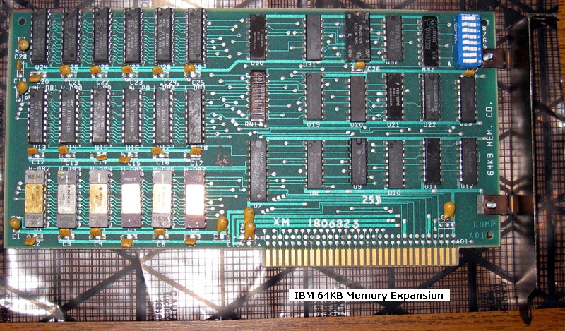
IBM 64KB Memory Expansion Option

This card provides 64 KB of conventional memory, via 2 banks of 32 KB.

Click here to see the layout of the 2 banks on the card.

RAM chips of type 4132 are used, of an access time rating of 200 ns (or faster).  Per the photo at here, a 4132 type chip is two slightly different chips in a stacked (piggybacked) arrangement.   4132 examples.

The switches control the starting address of the RAM.  Click here to see the settings.

You can have multiple of these cards in your IBM 5150 or 5160, providing that none of the RAM on a card has an address conflict with any other RAM (motherboard RAM or expansion card RAM).

The circuit diagram of this card is in appendix D of the AUG81 edition of the IBM 5150 Technical Reference manual.  (Link to manual here.)

As can be seen in the photo, this card has "64KB MEM. CD." printed on it.


5150_5160_64_memory_expansion.jpg


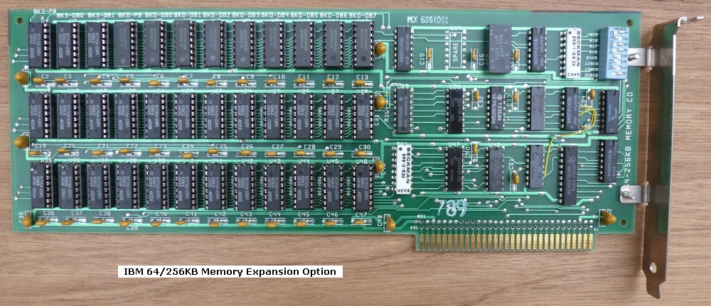
IBM 64/256KB Memory Expansion Option

This card provides up to 256 KB of conventional memory, via 4 banks of 64 KB.

Click here to see the layout of the 4 banks on the card.

RAM chips of type 4164 are used, of an access time rating of 200 ns (or faster), and of the type where pin 1 is not used (Not Connected).   4164 examples.

You can have multiple of these cards in your IBM 5150 or 5160, providing that none of the RAM on a card has an address conflict with any other RAM (motherboard RAM or expansion card RAM).

IBM has designed this card so that either, all of the RAM banks can be used, or just some of them.  4 of the 8 switches control that.
Note that on this card, simply removing an enabled bank's RAM chips does not disable the bank - the card still drives voltage onto the data bus if the bank is addressed for a read.
Use switches 5 through 8 to disable/enable the banks.

Click here to see some examples of two of these cards being used in an IBM 5150, and IBM 5160, to top up the conventional memory to 640 KB.

Click here to see the switch settings.

Click here to see IBM's technical document for the card.

As can be seen in the photo, this card has "64-256KB MEMORY CD" printed on it.


5150_5160_64_256_memory_expansion_option.jpg Click on photo for larger view


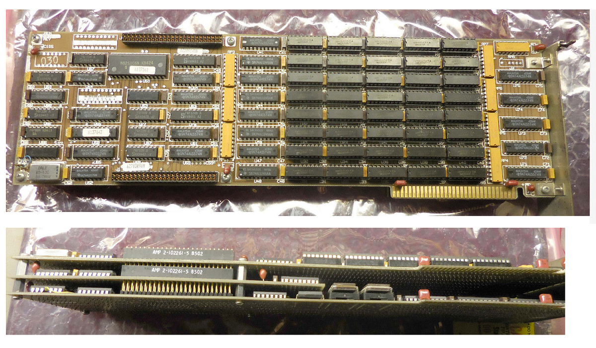
IBM 256KB Memory Expansion Option

This card provides up to 256 KB of conventional memory, via 4 modules, each module containing a bank of 64 KB.

Click here to see the layout of the 4 modules on the card.

Click here to see a photo of the card at www.vintagecomputer.net

You can have multiple of these cards in your IBM 5150 or 5160, providing that none of the RAM on a card has an address conflict with any other RAM (motherboard RAM or expansion card RAM).

Click here to see the switch settings.

Click here to see IBM's technical document for the card.

As can be seen in the photo, this card has "256KB MEMORY CARD" printed on it.


IBM 2MB Expanded Memory Adapter

This card provides 2 MB of XMA memory.  XMA is IBM's version of expanded memory - see the 'Expanded Memory Adapter (XMA)' section of here.

According to the document at here, the IBM 2MB Expanded Memory Adapter can be used in the IBM 5160.

Click here to see IBM's option instructions for the card.


IBM Fixed Disk Adapter

This is a hard disk drive (HDD) controller of the 'MFM' type.

Supplied in the IBM 5160.

It will work in the IBM 5150 if the motherboard's BIOS revision is the final one (10/27/82), but note the other important information at here.

There are three major variations of this card.

Click here for more information.


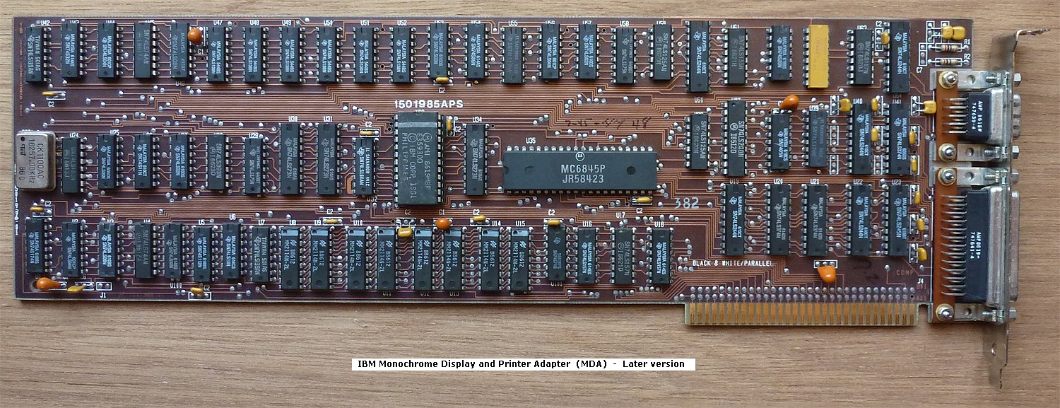
IBM Monochrome Display and Printer Adapter (MDA)

This card is designed to connect to IBM's 5151 monitor (MDA).

Connecting this card to a monitor that is not designed to accept MDA video/sync signals may damage the monitor.
The IBM 5153 monitor (CGA) and IBM 5154 monitor (EGA) are in that category (not designed for MDA signals).

When this card is fitted to an IBM 5150 computer (PC) or IBM 5160 computer (XT) as the only video card, the computer's motherboard switches (the 2 video card ones) must be set to  SW1:5 = OFF and SW1:6 = OFF

The included printer port is what later became referred to as a 'standard parallel port' (SPP) - see here.  The printer port is hardwired to I/O base address 3BC, and interrupt 7.

Click here to see IBM's technical document for the card.
Click here to see an early version of the card.
John Elliott's information is at here.


ibm_mda.jpg


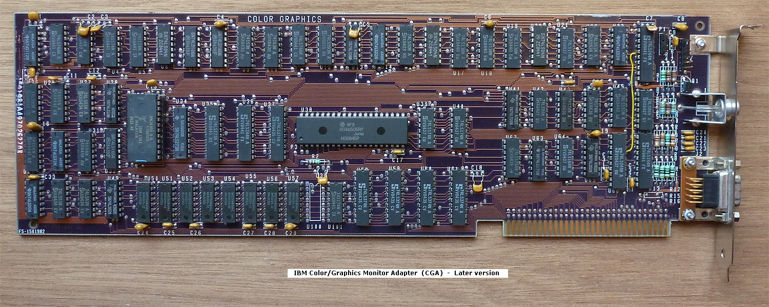
IBM Color/Graphics Monitor Adapter (CGA)

This card is designed to connect to IBM's 5153 monitor (CGA), via the 9-pin D connector.
Alternatively, a composite monitor (of type NTSC) can be connected to this card via the RCA jack.

Connecting this card to a monitor that is not designed to accept CGA video/sync signals may damage the monitor.
The IBM 5151 monitor (MDA) is in that category (not designed for CGA signals).

The IBM 5154 monitor (CGA and EGA) will accept the CGA video/sync signals from this card.

When this card is fitted to an IBM 5150 computer (PC) or IBM 5160 computer (XT) as the only video card, the computer's motherboard switches (the 2 video card ones) are to be set to  SW1:5 = ON and SW1:6 = OFF
Those settings result in an 80 column by 25 row display (at CGA).
If a composite monitor is connected to this card (via the RCA jack), 80 columns may result in text that is difficult to read on that monitor.  If that is the case, select the 40 column CGA mode by setting the computer's motherboard switches (the 2 video card ones) to  SW1:5 = OFF and SW1:6 = ON

Berg connector P1 provides an NTSC composite video signal and +12V, intended for an RF modulator.  As pictured at here, the IBM 5155's display unit sources its video signal (but not +12V) from P1.
Berg connector P2 is intended for a light pen.

If this card stops your computer from powering on, then suspect capacitor C8  (there being some history of it going short-circuit, overloading the power supply).

Click here to see IBM's technical document for the card.
Click here to see an early version of the card.
John Elliott's information is at here.


ibm_cga.jpg


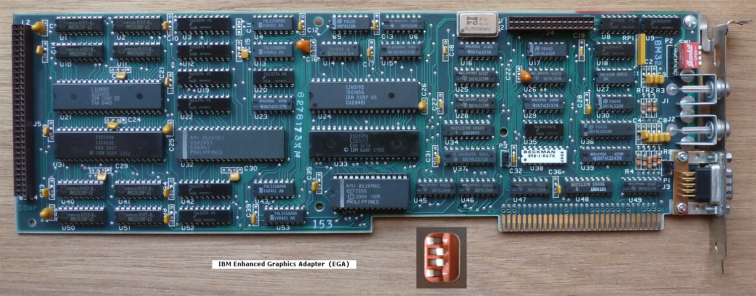
IBM Enhanced Graphics Adapter (EGA)

This card is primarily designed to connect to IBM's 5154 monitor (CGA and EGA).

If reconfigured via the red switch block, the card is capable of use (at reduced functionality) with the IBM 5151 monitor (MDA) or the IBM 5153 monitor (CGA).

Unlike on the IBM CGA card, the RCA connectors, J1 and J2, do not contain video for a composite monitor.  Instead, J1 and J2 are part of the card's feature connector functionality (J4).

When this card is fitted to an IBM 5150 computer (PC) or IBM 5160 computer (XT) as the only video card, the computer's motherboard switches (the 2 video card ones) must be set to  SW1:5 = ON and SW1:6 = ON
Those same motherboard settings are used even if you reconfigure the card for operation with an MDA or CGA monitor.

In the photo below, the optional Graphics Memory Expansion Card (plugs into J5) that provides additional video RAM, is not shown.  Without that add-on memory board, the EGA card has only 64 KB of video RAM, and that may result in some programs not displaying as intended (detailed here).  And CheckIt software has a problem with that as well (detailed here).

In the photo below, the switch positions shown on the red switch block suit an EGA monitor.

During the computer's Power-On Self Test (POST), the IBM EGA card will perform its own self test (a crude/basic one).  If the card finds a problem with itself (including video RAM), the card will cause the speaker to beep one of two possible error patterns: 1 long beep followed by 2 short beeps, or 1 long beep followed by 3 short beeps.

For this card to work in the IBM 5150, the 5150's motherboard will need to have the final BIOS revision (10/27/82) fitted.

Click here to see IBM's technical document for the card.

Some installation instructions are here.


ibm_ega.jpg


IBM Professional Graphics Controller (PGC)

From the IBM Systems Journal: "The IBM Professional Graphics Controller and Display were developed to meet the needs of engineers and scientists for an improved graphics capability in the Personal Computer environment. These units provide graphics systems with improved function, resolution, and color range, and at the same time they allow existing productivity software to be executed in an emulation mode."

This card is designed to connect to IBM's 5175 monitor.

IBM's announcement letter for this card is here.  That indicates suitability for the IBM 5155, IBM 5160, IBM 5161, and IBM 5170.  The IBM 5162 postdates this card, and may be suitable.

The card has two modes of operation, controlled by jumper W1:
* If the card is set for CGA emulation mode, the card behaves as a CGA card, and therefore, the motherboard video switches need to be set for CGA.
* If the card is set for native mode, the card is a secondary video card (the second video card on the motherboard).

John Elliott's information is at here.

Click here to see IBM's technical document for the card.


IBM Professional Graphics Controller.jpg


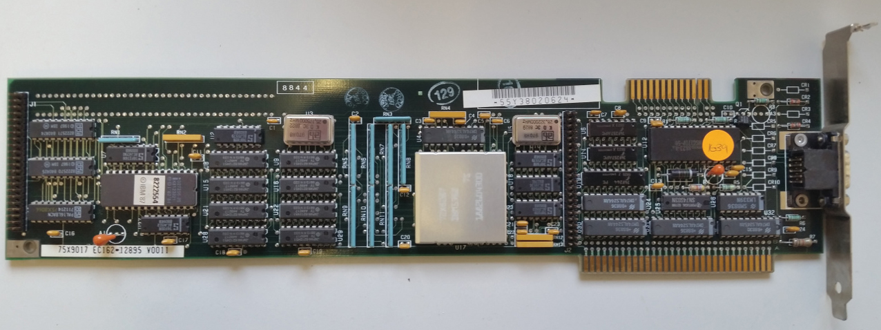
IBM PS/2 Display Adapter  (IBM Display Adapter)

"Functional equivalence with the Video Graphics Array (VGA) in IBM PS/2 Models 50, 60 and 80."

For this card to work in the IBM 5150, the 5150's motherboard will need to have the final BIOS revision (10/27/82) fitted.

IBM's announcement letter for this card is here.

CheckIt diagnostic software may report false errors during its 'video RAM' test of this card.  From memory, this is only when a monochrome VGA display is attached.


IBM PS2 Display Adapter.jpg


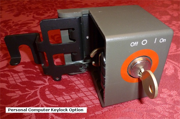
IBM Personal Computer Keylock Option

For 5150, 5160, 5161, XT/370 and 3270 PC.

Clips over computer's power switch.
Can only be fitted/removed when the keylock switch is in the ON position.
The key can only be removed when the keylock switch is in the OFF position.

IBM part number 2683177

IBM's installation instructions are here.
Some alternate installation instructions are here.

Box and contents photo at here.


5150_5160_keylock_option.jpg


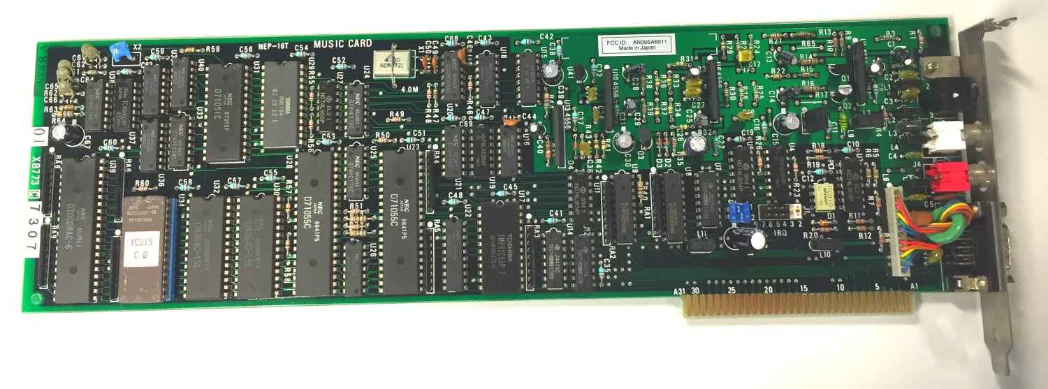
IBM PC Music Feature

Compatibility  
Installation Instructions  
Technical Reference (source: jens.hafner at the VCFF)
   
Additional information - 1 (source: jens.hafner at the VCFF)
Additional information - 2  


IBM PC Music Feature.jpg Click on photo for larger view


IBM Personal Computer Internal Modem 1200

Jumper Positions

Command Set - Quick Reference         (source: clh333 at the VCFF)